
Across the varying types of Audio-Visual (AV) design documentation commonly utilized for a typical integration project, it will be generally agreed that the system schematic serves as the central brain that ties everything together in depicting the overall functionality, performance and application of a proposed AV system within a particular space. From a design point-of-view, most supporting AV design drawings such as floor plan/RCP arrangements, rack layouts and elevations are usually built off the foundational schematic diagram. In the case of most standard room types, an experienced installer would be able to setup an entire AV system solely off of the schematic as his primary guide without the requirement for supplementary architectural arrangement layouts – with the exception of highly complex systems that involve multi-room linking, multiple floors etc. This is because the schematic contains every key aspect of a proposed system’s technical requirements for deployment at site. A qualitative system schematic, at the bare minimum, should reflect the following information:
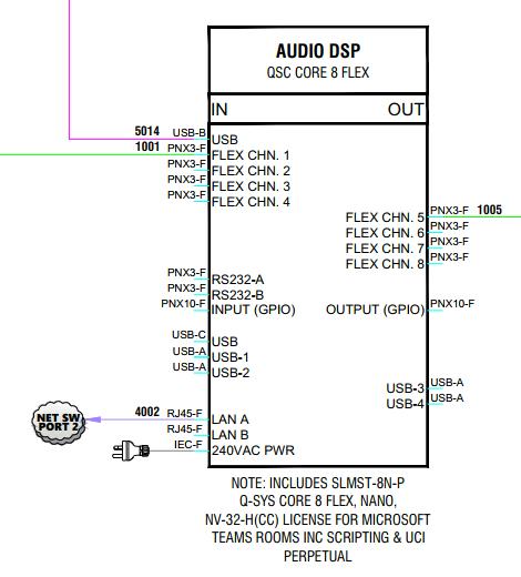
⦁ Equipment block models & individual connector inputs & outputs
⦁ Cabling detail & labels
⦁ Relevant descriptive information (i.e. device mounting details, existing/client-supplied devices, included kit accessories, speaker tapping & audio configurations etc.)
⦁ Equipment locations
⦁ Power & Data (PDO) allocation requirements
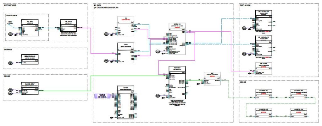
In our humble view, the defining element of a qualitative schematic lies in the accuracy & clarity of it’s equipment block framework. Every single connection port & connector type of a specific device should be shown, regardless of whether the port is actively being used in the system or is redundant. From a drafting perspective, this can be time-consuming, particularly for building large-scale switchers & processor blocks. However, there are 2 major reasons why this process will save time & cost in the long run. First, this provides an accurate overview of all available port options to the installer should he run into unexpected circumstances on site that require him to re-configure cabling port allocations to make the system work as required. Secondly, this approach will enable easier review for planned future upgrade expansions that are possible within the existing system environment. In addition, the As-Built schematic will also become the primary reference in the future for the installation status of a system that has been successfully deployed at site. Therefore, it is fairly evident how crucial the schematic diagram serves in provisioning a seamless process from design & planning through to installation, commissioning and post-installation maintenance. And hence, why it’s preparation should always be accorded careful, patient thought and never underestimated.
MENU
OFFICE
Triune Centre BO1-A 09, Menara 2, 3, Jalan Bangsar, KL Eco City 59200 Kuala Lumpur, Malaysia
Sales & General enquiries
MENU
OFFICE
Triune Centre BO1-A 09, Menara 2, 3, Jalan Bangsar, KL Eco City 59200 Kuala Lumpur, Malaysia
Sales & General enquiries
